Schemes of signal connection
In this chapter you can find a description of the analog device socket of E-140 from the point of view of external connections. Signal connection and unsoldering of sockets should be done by system user. The cable parts of sockets for signal connection are included in the complete set of regular delivery of program-technical complex.
The ranges of voltage, presented in tables at the description of signals, deduced on contacts of the sockets, are always reduced concerning AGND contact for analog signals.
|
||
|
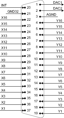
On the external module socket DRB-37M there are lines for the work with analog signals of input/output. The layout of socket contacts and the brief description of their values are give below on the picture and in the table:
The external analog socket DRB-37M
Signal |
Common point |
Direction |
Destination |
DAC<1...2> |
AGND |
Output |
DAC channel output 1
2. |
AGND |
--- |
--- |
Analog ground |
GND32 |
AGND |
Input |
Shoul be connected to ΐGND for all modes (in differential mode for increase of noise-immunity). |
X<1...16> |
AGND |
Input |
Noninverting input of channels 1...16; Working range of voltage ±10 V; Unusable inputs X<1...16> are recommended to be connected to AGND . |
Y<1...16> |
AGND |
Input |
Inverting input of channels 1...16; Working range of voltage ±10 V; Unusable inputs Y<1...16> are recommended to be connected to AGND . |
TRIG |
Digital |
Input |
Input of external digital signal synchronization (in the current realization of program-technical complex it is not used); |
To connect the signal sources from sensors of physiological information to the module you need to provide the common grounding mat of your PC and devices connected to it. You need to connect the contact 3 of module analog socket to the grounding mat of your devices.
The realization of program-technical complex allows to read the information from 16 various channels with differential scheme of connection.
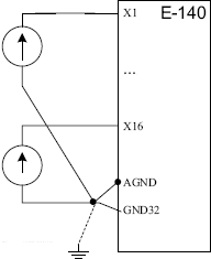
At the differential scheme of signal connection a voltage difference between two channel inputs is measured. At such connection a suppression of common-mode interferences, arising on lead, is provided not less than on 60 Db. However, you are to remember, that for correct work of the differential amplifier it is necessary, that a potential of each input concerning the ground (so-called a common-mode voltage) should not exceed the input range. Each signal source is connected to the channel by TWO wires. Noninverting ADC input is connected to the output source clamp, and inverting ADC input is grounded on the case of signal source. The common grounding mat is necessary to be layed with a separate wire. Below, on the pictures you can see two possible schemes of signal connection to the module.
|
||
|
|
||
|
At the differential connections the lines X means noninverting inputs, and the lines Y inverting.
Computer implementation > Measurements page > ADC measurements > Schemes of signal connection
© Samara-Dialog Ltd. 2004-2009 |


